Proton Computed Tomography
Background

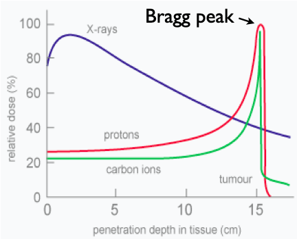
Fig. 1 The radiation depth profile. X-rays decay exponentially with depth. Protons deposit most of their energy just before stopping at the Bragg Peak. Carbon ions have less entry radiation and a sharper Bragg peak, but the damage they do behind the Bragg peak limits their usefulness.
Cancer is the second leading cause of death in the Western world. While surgery and chemotherapy can cure patients, these treatments are often augmented with radiation. Two of the common radiation modalities onocologists to choose from are x-rays and proton therapy.
X-rays are the easiest to produce, making them the inexpensive choice; however, their radiation damage profile is exponential with depth (see Fig. 1). That is, they deposit most of their radiation near the surface. Thus, physicians must spread out radiation delivery to give the tumor the largest dose without burning the skin.
Protons deliver the most tissue damage just before they stop; this is called the Bragg peak (see Fig. 1). The Bragg peak makes proton radiation a useful tool in treating head and neck tumors which are often surrounded by vital organs. For these situations, minimizing the treatment volume is often the difference between treatment and no treatment: the difference between life and death.
Proton Computed Tomography (pCT) will offer two unique advantages to patients getting treated with proton radiation. The first advantage is simple: pCT gives a lower radiation dose than that of x-ray Computed Tomography (xCT); however, this not the primary advantage.
To understand the primary advantage, it helps to know that radiation treatment planning requires a 3D image of the tumor, and currently, the only option is an xCT. It is probably not surprising that x-rays (which are photons) stop differently than protons (heavy, sub-atomic particles). This stopping-power difference is unfortunate because it means the 3D image (of x-ray stopping power) produced by the xCT is an ambiguous map for the stopping power of proton radiation. This translates into an increased margin of error for the depth of the protons which creates a larger treatment-volume. In the case of space-restricted tumors in the head and neck.
To avoid relapse in the cancer that caused the tumor, doctors apply a margin of error around the tumor to be sure its undetected SPELL tenticles are destroyed. For tumors far from vital organs, this acceptable: the body will recover from the radiation damage. However, tumors in the head and neck are often located too close to vital organs; that is, there is no room for doctors to prescribe the appropriate radiation margin. Unfortunately, these patients are denied treatment.
By eliminating the differential stopping power between xCT and pCT, oncologists will be able to perscribe smaller tumor margins. This means all patients will receive a lower radiation dose, and fewer patients will be denied treatment.
The Scanner

Fig. 2 (Upper) Photo of the phase 2 proton Computed Tomography scanner. (Lower) A representative proton path traveling through the forward position detector, head-phantom, rear position detector, and into the energy detector of the phase 1 scanner.

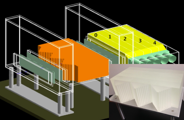
Fig. 3 The calibration phantom (orange) is shown between the tracker planes (and in the inset). The proton's final destination is the numbered, yellow, scintillating energy detectors.
The pCT scanner consists of two parts: the proton energy detector and the proton tracker.
The tracker is a silicon strip detector (SSD) charged with a moderate voltage. EXPLAIN BETTER When hit by a proton, scattered electrons flow down the strips and registering the coordinate. A position requires an x and y coordinate, and two positions are needed to record an angle. Thus, to measure the incoming and outgoing angle, the proton must pass through eight SSD detectors.
As the proton brakes to a stop, the scintillating energy detector gives off light. The proton stops in a series of five cesium-iodide (CsI) crystals. Each are wrapped in reflective tape and connected to photomultiplier tubes whose signal is processed to determine the proton's energy.
Energy Calibration
I worked with the calibration of the energy detector which involved the following steps:
Create low-intensity proton beam.
Take data with calibration phantom (see Fig. 3).
Reconstruct proton path from tracker data.
Determine the distance traveled in the calibration phantom.
Correlate this distance to light output.
For calibration, we need a low-intensity proton beam so that we are SPELL predominantly measuring single-proton events.
The calibration phantom shown in Fig. 3 was designed to spread uniformly energetic protons into energies that may be predicted by their path. A stepped triangular prism provides an surface on which error in the tracker will not greatly affect the detector path length. The tracker phantom has four removable blocks which allow us to create protons with energies across our detectable range.
The reconstruction of the proton path turns detector data into an entrance and exit ray. A proton event is eight SSD coordinants and the light output of the five energy detectors. First, tracker data is transformed from SSD strip number into detector coordinates SPELL. Periodically the incoming and outgoing rays would be misaligned, these events are attributed to proton scattering and discarded. The reconstruction of the remaining nearly-collinear rays, was solved to a series of linear equations.
The next step was finding the intersection of this geometric path with the calibration phantom, and converting it into the standard unit of stopping power: the water equivalent path length (WEPL). Determining this intersection was tedious, given the intricate triangular steps of the calibration phantom.
Because a proton deposits the maximum energy just before stopping (the Bragg peak), we maximize the precision of our energy measurement by calibrating with the light from the deepest crystal that contains the Bragg peak. IMPROVE
Summary
REMOVE Reinhard Schulte, our project's principle investigator, created the phase 0 scanner to include in his R01 grant application; it was made from spare parts and was added to improve the chances of his grant success. It worked; this proof of concept convinced the grant comittee of the project's viability. NOT NECESSARY
COMBINE Much more care and engineering went into the design of the phase 1 scanner. However, it was charactirized by its data acquisition bottleneck, and scans took between five and six hours. One can imagine how difficult this ordeal would be for a human receiving such a scan.
Among the many improvements in the phase 2 scanner was a series of custom designed integrated circuits to process current bursts from individual proton events on a single chip. This allowed us to take data at about 1 MHz which reduced the total scan time to between five and ten minutes.